Ajay K Agrawal
Robert F. Barfield Endowed Professor
Department of Mechanical Engineering
https://scholar.google.com/citations?hl=en&user=IogAX3cAAAAJ
https://Agrawal.people.ua.edu
Joshua Bittle
Associate Professor
Department of Mechanical Engineering
Associate Director – Center for Advanced Vehicle Technologies
https://jbittle.people.ua.edu
https://scholar.google.com/citations?user=dEM8ysoAAAAJ&hl=en
Paul Puzinauskas
Associate Professor
Department of Mechanical Engineering
Dr. Paulius V. Puzinauskas – College of Engineering (ua.edu)
https://scholar.google.com/citations?user=vOL5ASoAAAAJ&hl=en
Students:
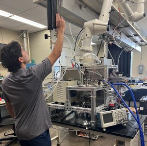
This facility consists of multiple laboratories to conduct fundamental studies of flow & combustion processes. Examples include small-scale experiments to study chemical kinetics of emerging fuels, fuel injector behavior, and engine intake/internal flows.
Innovative methods and approaches developed in these labs supplement ongoing research in ECL as well as provide scientific knowledge for a wide range of applications.
Ignition Delay. Ignition behavior of hydrocarbon fuels is typically studied in shock tubes and rapid compression machines. We have developed an alternate approach based on a constant volume combustion chamber (CVCC) to measure the ignition delay of fuels including emerging alternative fuels with complex molecular structures. CVCC achieves quasi-homogeneous conditions by minimizing the chamber volume and maximizing the fuel injection pressure. Our CVCC is designed to measure ignition delay of fuels at initial pressures and temperatures up to 50 bar and 1000°C, respectively.

CVCC is constructed of Inconel, and it is inductively heated to the desired temperature. A cylindrical chamber (20 mm OD x 75mm) inside it is filled with pressured air (or simulated gas mixture) at the specified pressure. After study conditions are reached, a precise amount of fuel is introduced into the chamber by a customized diesel injector. The dynamic ignition event is monitored by a high-speed pressure transducer to determine the ignition delay time. This system was commissioned recently, it is intended to study the ignition behavior of alternative fuels.
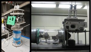
Injector Flows. In reciprocating engines, a fuel injectors’ rate of injection (ROI) during ramp-up, quasi-steady, and ramp-down periods is critically important to regulate the fuel supply and related combustion emissions. We have developed a novel device to measure ROI from each hole of a multi-hole injector (a) to determine hole-to-hole variations caused either by manufacturing imperfections or injector aging, (b) to identify effective multi-injection strategies, and (c) to develop novel fuel injector designs.
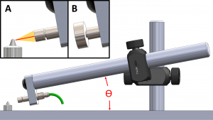
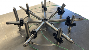
In the ROI setup, the fuel jet from each hole stagnates on a circular disk, and the resultant force is measured by a high-accuracy piezoelectric impulse force sensor (Kistler 9215A). Measurements at high-sampling rates are acquired to determine each hole’s ramp-up, quasi-steady, and ramp-down ROI. The apparatus consists of a flat plate, injector mount with heat sink, and sensor arm. The flat plate supports the injector protruded through a hole at the center. The sensor is mounted on a series of posts that allow for adjustment of the angle and distance from the injector hole(s). The design of the support plate with a circular slot facilitates the apparatus to be easily configured for different injector hole angles and target distances. The end of the sensor is threaded onto a circular disk of a chosen diameter to transfer force or impact from the fuel jet to the sensor.
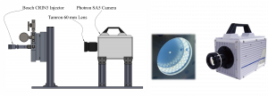
This lab also houses a constant volume, high-density, non-reacting spray chamber to characterize the spray evolution at conditions representative of a heavy-duty engine (>100 mm bore). The chamber is illuminated with high intensity LED strips located around the perimeter and the ambient density is varied by pressurizing the chamber with nitrogen. Camera access is facilitated via a Lexan window as if looking through a piston. Fuel is supplied pressurized with an air-driven, pressure multiplying pump. This facility has been used to compare injector flow field of convention diesel combustion (CDC) and peripheral fuel injection (PeFI) strategy developed at the University of Alabama.
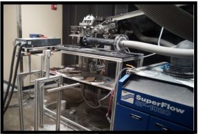
Engine Flows. This lab is dedicated to research and development of engine flow systems. Test platforms include a steady flow bench and two optical single cylinder reciprocating engines. An array of optical diagnostics and flow visualization and quantification tools can be integrated with these platforms. In particular, a dedicated PIV system with associated flow seeding equipment resides within the lab.
Steady Flow Test System, SuperFlow 1050 Probench with electronic pressure control and volumetric flow rate measurement, is used to quantify and/or optimize performance of individual flow components (e.g., intake manifold, valves, etc.) or complete flow systems. Pressure and flow rate measurements are used to determine flow discharge coefficients and thus, to identify performance limiting hardware and to improve the aerodynamic designs.
Flow system geometry parameters such as valve stem axis position relative to cylinder centerline can be used with measured or ideal flow rates to calculate angular momentum values that can be used as references for the measured values to calculate swirl or tumble coefficients along with valve discharge coefficients to support flow calculations for simulations such as GT-Suite or Ricardo Wave. These bulk flow measurements can also be compared to spatially integrated multi-dimensional CFD calculations to validate overall computational accuracy. An impulse angular momentum meter has been constructed for use with the system. This meter uses a honeycomb disk attached to a torque transducer to measure the torque required to remove any incoming angular momentum. Application of the integral conservation of angular momentum establishes that the measured torque is equal to the incoming rate of angular momentum. Adapters have been developed to position this meter in either the swirl or tumble axis.
A particular challenge associated with steady-flow PIV testing of full engine assemblies is the ability to add seeding without rapidly fouling optical access. We have carried out a detailed evaluation of various seeding methods to help address this challenge. Typical smoke-based techniques were found to foul the optical access after only several seconds of testing, making them impractical because of the time required to fully disassemble and clean the flow path. Dry seeding techniques can be used for longer duration, but seed is much more difficult to distribute evenly and presents a potential hazard when using a suction configuration. Our work evaluated several dry seeding materials and compared spatially-resolved PIV data integrated over the flow field to bulk impulse-momentum measurements. Further, suction and pressurized flow configurations were compared to show equivalency.
Single Cylinder Optical Engines are specifically designed to analyze spray and mixture preparation in gasoline injection systems, particularly for studying sprays for Gasoline Direct Injection (GDI) injectors. Currently the two engines are configured using components representing a
- Hyundai Lambda 3.8L (G6SA) V6, overhead cam engine with an 86 mm stroke and
- GM Gen V 5.3L V8 pushrod engine with a 92 mm stroke.
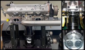
These reciprocating fully optical engines provide unsteady flow environments to more realistically represent the flow conditions of actual engines. Engines utilize transparent cylinder liners and extended Bowditch pistons with transparent tops to provide full optical access to apply a suite of optical diagnostic techniques available in ECL. Both engines could be modified to represent other engine platforms although the stroke is limited to one of the two existing values. The engines are powered by a 15 HP electric motor controlled using a four-quadrant variable frequency drive. The oiling coolant systems are both equipped with pressure control and electrical heat temperature control. The fuel systems are fully configurable allowing behavior comparisons of different fuels or characterizing the effects of various operational parameters such as fuel pressure and timing or fuel-injector geometry.
Research Examples:
Related Publications:
- Edward F. Bogdanowicz, Allen Loper, Joshua Bittle, and Ajay K. Agrawal, 2024, “Experimental Study of Peripheral Fuel Injection for Higher Performance in Diesel Engines,” International Journal for Engine Research, p.14680874241232007.
- Voris, A.R. and Puzinauskas, P., “Characterization and Comparison of Steady-Flow Techniques Used for Engine Airflow Development,” SAE Technical Paper 2021-01-1151, 2021.
- Suttle, A., Fisher, B., Parnell, D., Bittle, J. (2018) Demonstrating a direct-injection constant-volume combustion chamber as a validation tool for chemical kinetic modeling of liquid fuels. Paper presented at 2018 ASME Internal Combustion Engines Division Fall Technical Conference, San Diego, California, ICEF2018-9729.
- Fisher, B., Allen, J., Hancock, R., Bittle, J. (2017). “Evaluating the potential of a direct-injection constant-volume combustion chamber as a tool to validate chemical-kinetic models for liquid fuels.” Combustion Science and Technology. 159:1, 1-23.