Ajay K Agrawal
Robert F. Barfield Endowed Professor, Department of Mechanical Engineering
https://scholar.google.com/citations?hl=en&user=IogAX3cAAAAJ
https://Agrawal.people.ua.edu
Students:
Kayla Bell, Apurav Gupta, Ashley James, Mitch Johnson, Dalton Langner, Robert Miller, Shaon Talukdar, Jonathan Tobias
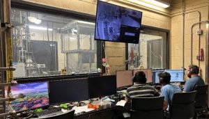
This lab is dedicated to advanced combustion research on gas turbines for power generation, aviation, and rocket propulsion. The lab is properly ventilated for combustion experiments at low- to high pressures using various gaseous and liquid fuels. Three large capacity vertically oriented hoods are available to safely exhaust the combustion products. Low-pressure, small-scale experiments can be performed within the test cell. However, high-pressure experiments are operated remotely from adjacent control rooms with large bullet-proof windows for visual observation.
Rotating Detonation Engines (RDE) studies focus on improving pressure gain and reducing flow nonuniformities at RDE exit for effective integration of RDEs with the downstream hardware. The lab features an annular RDE for power generation and a radial or disk RDE for rocket propulsion. The RDE designs have evolved over the years, and each RDE can be fired with various fuel and oxidizer combinations available via compressed gas cylinders housed in the lab. Measurements are obtained by CTAP, ion, PCB, and Kulite probes, and optical diagnostics including
- High-speed particle image velocimetry (PIV) at up to 100 kHz
- Rainbow schlieren deflectometry at up to 300 kHz,
- Broadband imaging at up to 250 kHz,
- Chemiluminescence imaging at up to 50 kHz.
Thermoacoustic Instabilities are investigated using a passive technique pioneered in the lab: ring-shaped porous structures to shield the reaction zone from corner, central, and toroidal vortical structures formed in swirl-stabilized combustion systems. The lab features Lean Direct Injection (LDI) and Lean Premixed (LPM) combustion systems respectively for aviation and power generating gas turbines. Experimental capabilities include preheated air temperatures up to 600 K and pressures of up to 10 atm. Instrumentation includes flame and spray diagnostics by
- High-speed particle image velocimetry
- Simultaneous OH* and CH* chemiluminescence imaging,
- Mie-imaging and diffuse background imaging (DBI),
- Phase-Doppler particle analysis.
Combustion Diagnostics focuses on high-speed intrusive and non-intrusive measurements in challenging environments. Recent projects include:
- Rainbow Schlieren Deflectometry (RSD),
- Simultaneous OH* and CH* Chemiluminescence Imaging,
- High-Speed PIV of Periodic Supersonic-Subsonic Flows,
- Diffuse Background Imaging (DBI) of Dispersed Sprays.
- Thermal Compensation for Absolute Pressure Measurements in RDEs.
Rotating Detonation Engines
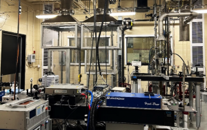
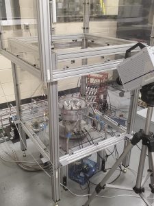
Rotating Detonation Engine (RDE) research facility consists of compressed gas storage systems (2200 psi) with manifolds to supply high flow rates of oxidizer (air and/or oxygen) and fuel (methane and/or hydrogen) for the experiment. Each reactant gas supply system a dome regulator, a calibrated sonic nozzle, and an electro-pneumatic valve upstream of the RDE to promptly turn on/off the flow. Systems inside the test cell include (a) flow measurement and control, (b) H2/O2 pre-detonator, (c) flow seeding system for PIV, and (d) multiple imaging and optical diagnostics. The operation of the complete experimental setup is automated and controlled from monitoring stations placed outside the test cell, behind bullet proof observation windows. These common facilities support two RDC experimental platforms:
- Annular RDE for power generating gas turbines
- Disk or radial RDE for rocket propulsion.
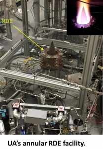
Annular RDE (ARDE) test stand is vertically assembled inside a Lexan enclosure, and the test chamber is equipped with purging nitrogen lines, ventilation air supplies, and exhaust to safely release the combustion products into the environment. ARDE consists of a modular combustor with multiple concentric spools and a circular center body. Each concentric spool has an inner diameter of 100 mm, and the diameter of the center body is 80 mm, resulting in an annular gap of 10 mm. The height of the annular channel is 114 mm, much greater than the expected height of the detonation front. Oxidizer from the oxidizer plenum is delivered into the combustor through 60 equally spaced injection holes, each with a diameter of 3.18 mm. Fuel is injected through an array of 30 holes, each with a diameter of 2.39 mm.
GTC-4a
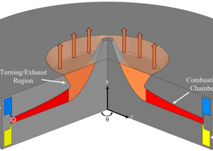
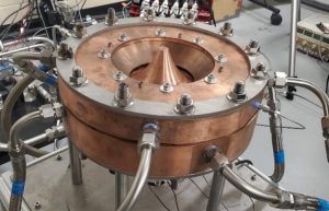
Radial RDE (RRDE) is a modular hardware with an integrated aerospike to turn the flow from radial to axial to maximize thrust production. The top and bottom support plates house the instruments, position the remaining components, and provide structural strength to sustain loads encountered during testing. Reactant plenums and injection schemes for fuel and oxidizer are created by the respective injector rings. Reactants are supplied axially through continuous slits that encircle the combustion chamber at a radius of about 104 mm. The system is operated by a National Instruments C-RIO chassis for precise control of timings. A C-RIO, along with a separate C-DAQ, are used for all data acquisition purposes.
GTC-6(a) (video); can speed up video to 2x and reduce length as appropriate.
GTC-6(b) (video)
Research Example(s):
- Presentation – Integrating a Rotating Detonation Combustor with a
- Performance of a Radial Rotating Detonation Engine with an Aerospike
Related Publications:
Journal:
- Raj, Piyush, Talukdar, Shaon, Dalton, Meadows, Joseph, and Agrawal, Ajay K., 2024, “Performance Evaluation of Different Rotating Detonation Combustor Designs using Simulations and Experiments,” ASME Journal of Engineering for Gas Turbines and Power, 146(4).
- Gupta, Apurav, Miller, Robert, Bell, Kayla, Langner, Dalton, and Agrawal, Ajay K., 2024, “Quantitative Measurements in the Exhaust Flow of a Rotating Detonation Combustor Using Rainbow Schlieren Deflectometry,” ASME Journal of Engineering for Gas Turbines and Power.
- Langner, Dalton, Gupta, Apurav, James, Ashley, and Agrawal, Ajay K., 2024, Performance Characterization of a Radial Rotating Detonation Combustor with Axial Exhaust, ASME Journal of Engineering for Gas Turbines and Power.
- Talukdar, Shaon, Langner, Dalton, Gupta, Apurav, and Agrawal, Ajay K., 2024, “Flow and Performance Characterization of Rotating Detonation Combustor Integrated with Various Convergent Nozzles,” AIAA Journal,
- Talukdar, Shaon, Langner, Dalton, Gupta, Apurav, and Agrawal, Ajay K., 2024, “Performance characteristics of a rotating detonation combustor exiting into a pressurized plenum to simulate gas turbine inlet,” ASME Journal of Engineering for Gas Turbines and Power, 146(4).
- Raj, Piyush, Talukdar, Shaon, Dalton, Langner, Gupta, Apurav, Meadows, Joseph, and Agrawal, Ajay K., 2024, Validation of rotating detonation combustor CFD for predicting unsteady supersonic-subsonic flow field at the exit,” ASME Journal of Engineering for Gas Turbines and Power, 146, pp. 041012-1.
- Bell, K., Schwer, D. and Agrawal, A.K., 2023. Profiling cross-sectional area of a radial rotating detonation combustor to increase pressure gain. Aerospace Science and Technology, 133, p.108096.
- Tobias, J.R. and Agrawal, A.K., 2023. Flow Development in Radial Plane of Rotating Detonation Engine Integrated with Aerospike. Journal of Propulsion and Power, 39(3), pp.318-330,
- Tobias, J., Depperschmidt, D., Welch, C., Miller, R., Uddi, M., Agrawal, A.K. and Daniel, R., 2019. “OH* Chemiluminescence Imaging of the Combustion Products from a Methane-Fueled Rotating Detonation Engine,” ASME Journal of Engineering for Gas Turbines and Power, 141(2), p.021021.
Thermoacoustic Instabilities
Thermoacoustic instability research facility consists of a modular test rig which can be configured for operation in lean premixed (LPM) or lean direct injection (LDI) combustion mode; an optional high-pressure chamber facilitates operation at up to 10 atmospheres in either configuration. A large air compressor supplies dehumidified air to the combustor, and a compressed gas storage system supplies high-pressure air for liquid fuel atomization.
Systems inside the test cell include (a) flow control hardware, (b) a preheater capable of 600 K air temperatures, (c) flow seeding system for PIV, (d) imaging and optical diagnostic systems, and (e) exhaust and ventilation systems. The operation of subsystems is automated and controlled through Labview based data acquisition and control systems. The monitoring stations and computers for control are placed outside the test cell. Additional safety equip6ment facilitates manual operation at ambient conditions within the test cell.
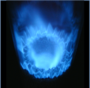
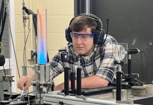
Lean Premixed Combustion employs a mixing channel to facilitate reactant mixing upstream of the combustor. A dump plane attachment featuring selectable swirlers is attached downstream of the mixing length, upon which an optically accessible quartz combustor and acoustic probe attachment point resides. In the case of high-pressure chamber, a linear traversing ram controls chamber pressure with a variable geometry throat at the chamber exit. This equipment configuration has been employed extensively to study the impact of swirler geometry and porous media structure on thermoacoustic instability and combustion dynamics at ambient and elevated temperatures and pressures.
Lean Direct Injection Combustion employs a NASA-derived swirl-venturi injection scheme to enhance reactant mixing immediately prior to reaction. A plenum and dump plane attachment featuring this injector is attached downstream of the common mixing tube, upon which a quartz combustor and probe port resides. Liquid fuel is supplied via a Delevan SNA-type injector that uses atomizing air to produce a fine, conical spray. This spray subsequently flows into the swirling primary air flow, further enhancing secondary atomization.
Methane or natural gas enters the primary air flow within the plenum to act as a more readily ignitable mixture, prior to the onset of liquid fuel flow, and is disabled upon reaching quasi-steady operation. Under acoustically stable conditions, very few droplets are visible downstream of the dump plane, but the presence of thermoacoustic coupling produces dramatic oscillations in the atomization process. This equipment configuration has been employed recently to study porous media at mitigating combustion dynamics.
Research Example(s):
Related Publications:
Journal
- Johnson, Mitchell, James, Ashley, and Agrawal, Ajay K., 2024, Effect of Insert Porosity on Combustion Instability in a Lean Premixed Combustor Analyzed by a POD-Based Phase Reconstruction Technique, ASME Journal of Engineering for Gas Turbines and Power,
- Williams, L. Justin, Meadows, J., and Agrawal, A.K., 2016, “Passive Control of Thermo-acoustic Instabilities in Swirl-Stabilized Combustion at Elevated Pressures,” International Journal of Spray and Combustion Dynamics, 8(3), pp. 173-182.
- Meadows, J., and Agrawal, A.K., 2015, “Porous Inserts for Passive Control of Noise and Thermo-acoustic Instabilities in LDI Combustion,” Combustion Science and Technology, vol. 187:7, pp 1021-1035, doi=10.1080/00102202.2014.993031.
- Borsuk, A., Williams, L.J., Meadows, J., and Agrawal, A.K., 2015, “Swirler Effects on Passive Control of Combustion Noise and Instability in a Swirl-Stabilized Combustor,” ASME Journal of Engineering for Gas Turbines and Power, vol. 137, pp. 041504-1 to 7, DOI: 10.1115/1.4028613.
- Meadows, J., and Agrawal, A.K., 2015, Time-Resolved PIV Measurements of Non-Reacting Flow Field in a Swirl-Stabilized Combustor Without and With Porous Inserts for Acoustic Control,” ASME Journal of Engineering for Gas Turbines and Power, vol. 137, pp. 041501-1 to 10.
- Meadows, J., and Agrawal, A.K., 2015, “Time-Resolved PIV of Lean Premixed Combustion without and with Porous Inert Media for Acoustic Control,” Combustion and Flame, vol. 162, pp. 1063-1077.
- Sequera, D., and Agrawal, A.K., 2012, “Passive Control of Noise and Instability in a Swirl-Stabilized Combustor with the Use of High-Strength Porous Insert,” Journal of Engineering for Gas Turbines and Power, vol. 134, 051505, (11pp).
Combustion Diagnostics
We are interested in novel diagnostics for challenging combustion experiments, some of which are outlined here.
Rainbow-Schlieren Deflectometry (RSD). RSD technique has been pioneered by our group since its inception in 1993. RSD utilizes a computer-generated rainbow filter and image processing techniques to obtain quantitative distributions of refractive index difference across the whole field. Because the refractive index difference can be related to the scalar quantities, the RSD technique has been used for various applications, including temperature measurements in a liquid pool, temperature and concentration measurements in laminar gas jets and flames, density measurements in an under-expanded air jet, turbulence measurements in a helium jet, fuel-air mixing in high-pressure diesel sprays, and most recently, to characterize the exhaust of a rotating detonation engine. Refer to the following publication for a detailed description of RSD.
- Agrawal, A.K., and Wanstall, C.T., 2018, Rainbow Schlieren Deflectometry for Scalar Measurements in Fluids Flows, Journal of Flow Visualization and Image Processing, 25(3-4).
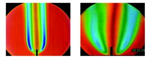 RSD image of a hydrogen jet flame in normal gravity (left) and microgravity (right).
Recently, we have utilized non-intrusive rainbow schlieren deflectometry with tomography to quantitatively characterize the exhaust plume of an RDE in terms of 3D density measurements. Multiple views required for tomography were obtained at 300 kHz by a single high-speed camera while the detonation/oblique shock wave rotated in the field of view. Tomographic reconstruction was applied to obtain local 3D refractive index fields, and subsequently, local 3D density fields revealing a spiral trailing structure behind the oblique shock structure rotating around the aerospike in a helical manner.
- Apurav Gupta, Robert S. Miller, Kayla M. Bell, Dalton G. Langner, and Ajay K. Agrawal, 2024, “Quantitative Measurements in the Exhaust Flow of a Rotating Detonation Combustor Using Rainbow Schlieren Deflectometry,” ASME Journal of Engineering for Gas Turbines and Power.
Simultaneous Chemiluminescence (CL) Imaging. CL imaging of multiple combustion species requires an image doubler or a beam splitter, which inherently introduces parallax and/or path-length errors in the image produced. Multiple cameras, each viewing a different species, also introduce parallax and line-of-sight (LOS) errors because each camera has a different view angle. Building upon the two-color pyrometry (2CP) technique pioneered in the High-Pressure Spray lab, we have developed a versatile optical setup to image any two different combustion species using a single high-speed camera.
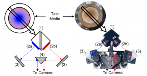
The technique provides spatially resolved measurements in reacting flows with large spatial and temporal variations. As shown in the figure, CL signal from the test media is split by a beamsplitter oriented perpendicular to the camera lens for light collection. This arrangement enables the two sub-images to be symmetrically divided onto the camera lens. Light from the beam splitter passes through two narrow bandpass filters, with transmissivity peaks at the emissivity wavelength for each species observed.
- James, A.M., and Agrawal, A.K., 2023. Spatially resolved chemiluminescence imaging of multiple combustion species using a single high-speed camera. Measurement Science and Technology, 34(12), p.125305.
High-Speed PIV of Periodic Supersonic-Subsonic Flows. Applying PIV in high-speed reacting flows with moving shocks (relevant to RDEs) is inherently complex because of the challenges such as spatio-temporal seed density variations, non-monodispersed particles, and particle agglomeration. Our PIV system utilizes a double-head Photonics Industries (DSH-532-35) laser system where each head emits 532 nm laser beam at 100 kHz with an approximate laser pulse duration of 15 ns to illuminate the Region of Interest (ROI). The laser beam passes through spherical and cylindrical lenses to generate a laser sheet.
We have shown that 200 nm ZrO2 particles can properly follow the flow except in regions across the moving oblique shock wave. The images are acquired at 200 kHz by a Photron SA-5 Fastcam CMOS high-speed camera fitted with a Sigma 105 mm focal length lens. A 532 nm band-pass optical filter was mounted on the camera lens to transmit the light scattered by the seed particles. The PIV timing sequence is implemented via a synchronizer controlled by the Insight 4G Data Acquisition, Analysis, and Display software from TSI.
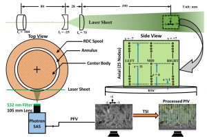 Optical setup for PIV
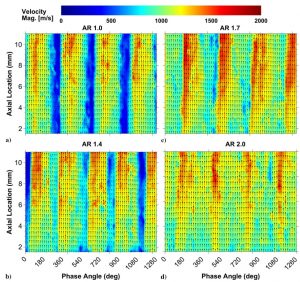 Temporal evolution of velocity fields at a mid-circumferential node
- Talukdar, Shaon, Langner, Dalton, Gupta, Apurav, and Agrawal, Ajay K., 2024, “Flow and Performance Characterization of Rotating Detonation Combustor Integrated with Various Convergent Nozzles,” AIAA Journal.
Diffuse Background Imaging (DBI) of Dispersed Sprays. DBI has primarily been used to investigate diesel and other automotive sprays. Instead, we are focused on DBI to analyze relatively dispersed gas turbine sprays. Our DBI optical setup includes a single-pulsed broadband LED (controlled by a Lightspeed Technologies driver) placed at the focal point of a Fresnel lens with an effective diameter of 100 mm and a focal length of 71 mm to generate parallel beams of light. An engineered diffuser with a divergence angle of 5 degrees is used to obtain uniform diffuse background illumination. High-speed imaging is then used to capture the spray at non-reacting and reacting conditions. Detected liquid presence in a spray appears darker than the background.
Research Examples:
- Presentation – QUANTITATIVE MEASUREMENTS IN THE EXHAUST FLOW OF A ROTATING DETONATION COMBUSTOR
- Presentation – Flow Characterization of a Rotating Detonation Combustor Integrated with Various Convergent Nozzles
- Simultaneous Imaging of OH* and CH* Chemiluminescence in the Exhaust of a Rotating Detonation Engine
Related Publications:
Journal:
- Apurav Gupta, Robert S. Miller, Kayla M. Bell, Dalton G. Langner, and Ajay K. Agrawal, 2024, “Quantitative Measurements in the Exhaust Flow of a Rotating Detonation Combustor Using Rainbow Schlieren Deflectometry,” ASME Journal of Engineering for Gas Turbines and Power.
- Talukdar, Shaon, Langner, Dalton, Gupta, Apurav, and Agrawal, Ajay K., 2024, “Flow and Performance Characterization of Rotating Detonation Combustor Integrated with Various Convergent Nozzles,” AIAA Journal.
- James, A.M., and Agrawal, A.K., 2023. Spatially resolved chemiluminescence imaging of multiple combustion species using a single high-speed camera. Measurement Science and Technology, 34(12), p.125305.
- K. L. Johnson, C. T. Wanstall, Joshua A. Bittle, and Ajay K. Agrawal, 2023, “Application of diffuse background illumination for statistical description of a twin-fluid spray,” Atomization and Spray, 15 pp, 33(12),
- Wanstall, C.T., Bittle, J.A. and Agrawal, A.K., 2021, Quantitative Concentration Measurements in a Turbulent Helium Jet using Rainbow Schlieren Deflectometry, Experiments in Fluids, 62(3), pp.1-13.
- Parker, A., Wanstall, C., Reggeti, S., Bittle, J., and Agrawal, A.K., 2020, Simultaneous Rainbow Schlieren Deflectometry and OH* Chemiluminescence Imaging of a Diesel Spray Flame in Constant Pressure Flow Rig, Proceedings of the Combustion Institute, 38(4), pp.5557-5565.
- Wanstall, C., Agrawal, A. K., and Bittle, J. A., 2019, Phase boundary detection in transient, evaporating high-pressure fuel sprays by rainbow schlieren deflectometry. Applied Optics, 58(25), 6791-6801.
- Agrawal, A.K., and Wanstall, C.T., 2018, Rainbow Schlieren Deflectometry for Scalar Measurements in Fluids Flows, Journal of Flow Visualization and Image Processing, 25(3-4).
- Wanstall, C.T., Agrawal, A.K. and Bittle, J.A., 2017. Quantifying liquid boundary and vapor distributions in a fuel spray by rainbow schlieren deflectometry, Applied Optics, 56(30), pp.8385-8393.
- Kolhe, P., and Agrawal, A.K., 2009, “Abel Inversion of Deflectometric Data: Comparison of Accuracy and Noise Propagation of Existing Techniques,” Applied Optics, vol. 48, No., 20, pp 3894-3902.
- Kolhe, P., and Agrawal, A.K., 2009, “Density Measurements in a Supersonic Microjet using Miniature Rainbow Schlieren Deflectometry,” AIAA Journal, vol. 47, vol. 4, pp. 830-838.
- Satti, R., Kolhe, P., Olcmen, S., and Agrawal, A.K., 2007, “A Miniature Rainbow Schlieren Deflectometry System for Scalar Measurements in Micro Jets and Flames,” Applied Optics, vol. 46, No. 15, pp. 2954-2962.
- Wong, T., and Agrawal, A.K., 2006, “Quantitative Measurements in an Unsteady Flame using High-Speed Rainbow Schlieren Deflectometry,” Measurement Science and Technology, vol. 17, pp. 1503-1510.